
Also Called SMT assembly line
SMT is the new technology to produce the circuit. Many years ago, People produce circuit use wires, so electronic product is big and hard to use and take with. So the circuit develop direction is become smaller, then People inveted the PCB, it can put the circuit on a small PCB, and then the components invented to out the resistors, capacitors on the PCB. All technology rated in this process is SMT.
Traditional electronic components compressed into a volume of only a few tenths of the device directly to the surface assembly components paste, printed on the printed circuit board surface location of the assembly technology.
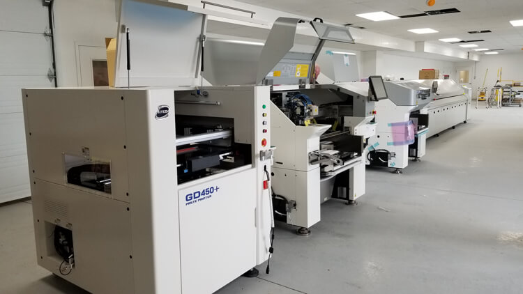
Compared with the traditional process, SMT has high density, high reliability, low cost, miniaturization, sound field automation and other five characteristics. The following is our Canada customer's JUKI RS-1R Assembly line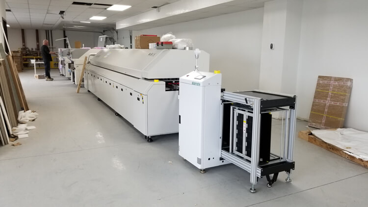
Types of SMT production lines
SMT production line can be divided into two types, according to the degree of automation can be divided into automatic production lines and semi-automatic production lines; in accordance with the size of the production line can be divided into large, medium and small production lines.
Automatic production line refers to the entire production line equipment are fully automatic equipment, through the automatic board machine, buffer cable and unloading machine all the production equipment with a production line;Normally it is with these machines: PCB loader, Auto smt stencil printer, PCB converyor, Pick and Place Machine, SMT reflow oven, AOI.
Semi-automatic production line is the main production equipment is not connected or not fully connected, the press is semi-automatic, the need for manual printing or manual loading and unloading PCB.normally is was with these machines: semi auto solder paste printer, PCB conveyor, Pick and Place Machine, Reflow oven, PCB conveyor, semi auto AOI.
SMT production line of the main components are: by the surface assembly components, circuit boards, assembly design, assembly process;
The main production equipment, including printing machines,glue dispensers, placement machines, reflow soldering ovens and wave soldering machine. Auxiliary equipment, testing equipment, repair equipment, cleaning equipment, drying equipment and materials storage equipment.
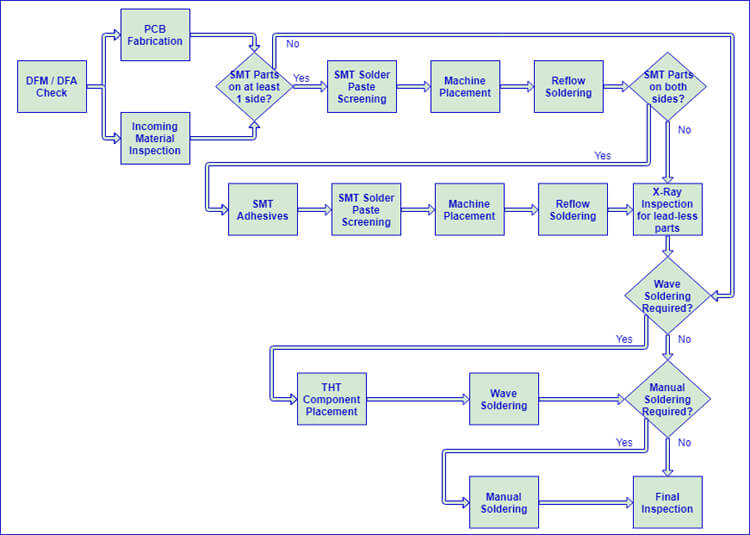
One of the most important factors in the overall efficiency of each PCB Production project is the client’s understanding of SMT Production process. The number of steps involved in the PCB Production process depends upon the specific nature of the project in question, as illustrated by the Automatic SMT Production Line flow chart below, and each of these steps is explained briefly in the following sections. For simplicity’s sake, some intermediary stages are not shown in this flow chart; for example, each stage includes individual inspection upon completion. Being familiar with this process in advance, a savvy engineer can design their PCB specifically for a fast and efficient assembly process by minimizing the overall number of steps required.
Automatic SMT Production Line Flow Chart:
PCB Loader➡SMT Stencil Printer➡PCB Conveyor➡SPI➡Pick and Place Machine➡AOI➡SMT Reflow Oven➡AOI➡PCB Unloader➡DIP Component Insert Line➡Wave Soldering Machine➡THT PCB unloader
Once a turnkey order is released to PCB Production Company’s production team, their very first task is the validate the design through a thorough DFM / DFA Check process. These checks include verification of consistency across different design documents (i.e. BoM, Gerbers, Centroid, etc.), part spacing, footprint accuracy, and clear orientation markings. The main objective of this procedure is to minimize as much as possible the potential for design errors to affect the finished product, which acts to protect PCB Assembly Company’s clients against the additional time and cost involved with board-level rework.
Clients should watch for emails from PCB Production Company’s production team over course of the first one or two days after placing an order. If any issues or discrepancies are detected during this initial check, the production coordinator for the order in question will reach out to the client directly for resolution. Generally, an itemized report will be sent for response, and the order will be placed on hold pending full confirmation, so it is important to reply to these questions as soon as possible in order to avoid delays.
Once the initial DFM / DFA Check is complete, the order proceeds to the PCB Fabrication stage. Here the bare PCB is formed through multiple stages of Material Lamination, Drilling and Copper Deposition / Etching, depending upon the design requirements; the stencil for solder paste screening (discussed below) is also created during this stage. The Solder Mask and Surface Finish, which aid in PCB assembly, are then added to the board, and finally, the Silkscreen is printed over all. Once the boards are fully formed, Electrical Testing is conducted against a client’s Netlist file, to verify 100% conformance with design requirements. Finally, Tab Routing or V-Scoring defines the profile of each individual PCB within the fabricated panel, providing for ease of separation after PCB Production is completed.
As the focus of this article is the SMT Production Line, the above is only a brief overview of PCB Fabrication, which is an intricate process in its own right. For a comprehensive discussion of SMT Production Line’s process and capabilities regarding PCB Fabrication, please see the DFM Guidelines document.
SMT Production Line’s Parts Procurement team works concurrently with their PCB Fabrication team to ensure that all assembly materials are received and ready for use as soon as the bare PCBs are ready for assembly. As parts are received at PCB Assembly Company’s production facility, Their Incoming Quality Control (IQC) team conducts a thorough inspection before warehousing any particular material or component. Inspections include sample operational testing as well as date code verification and entry into a software material management system. Their sophisticated software management system ensures that rules of first-in-first-out are strictly followed, and that parts used in PCB Assembly are always in good working order.
The combined efforts of SMT Production Line’s IQC and Parts Procurement teams should ensure that all parts used in PCB assembly are of the highest quality so that their clients can be confident in the overall shelf-life of their products.
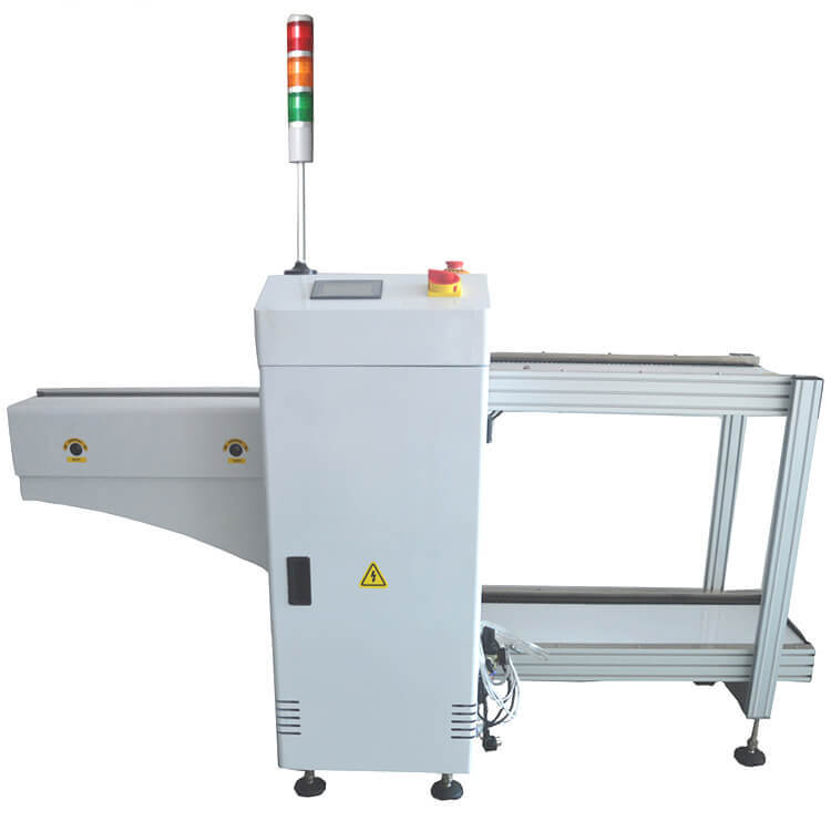
This Machine is used to loading PCB to SMT Stencil Printer automaticly. Worker put the PCB(like 100pcs each time) in the magazines and load to the PCB loader, PCB loader will sending the PCB to the SMT Stencil Printer one by one.
The first step in the actual PCB Assembly process is the application of solder paste to the bare PCBs. Here the stainless-steel stencil that was created during PCB Fabrication is fit over the bare board, leaving only the pads for assembly of surface-mount components uncovered. The stencil is held in place by a mechanical fixture, and an applicator moves over the surface of the board to meticulously distribute solder paste over those uncovered spaces. PCB Assembly Company’s quality control team then performs a thorough inspection to ensure that the solder has only been applied to the necessary areas, and that all pads are covered with a sufficient amount of paste. For double-sided SMT boards, this process will need to be performed individually for each side, as indicated in the above flowchart.
PCB Assembly Company’s solder of choice can be SAC305, which is a Lead-Free alloy containing 96.5% tin, 3% silver, and 0.5% copper, and is compliant with the RoHS, REACH, and JEIDA directives. Solder choice also can be Sn99.3Cu0.7, They can use the paste version of this kind material for reflow soldering, and solid versions for manual and wave soldering.
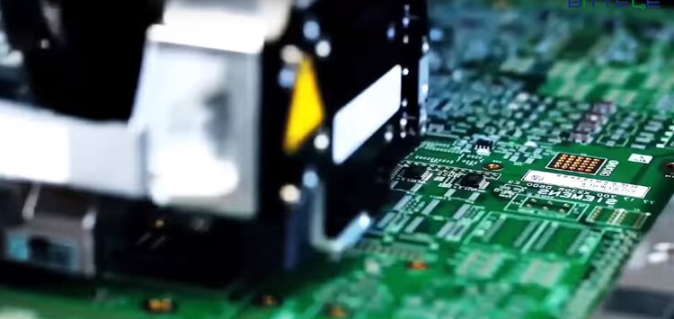
Once solder paste is applied to the bare PCBs, they are moved to PCB Assembly Company’s automated Pick & Place machines for the actual mounting of components on their associated pads. Part placement is 100% machine automated for maximum accuracy and efficiency, and uses the project’s Centroid file for component coordinates and rotation data. The boards are again inspected after components have been mounted to ensure all placements are accurate before the soldering process begins.
This stage might need to be performed multiple times, depending upon the specifics of a given project. Double-sided SMT boards require one round of placement for the top and one for the bottom, and projects requiring wave soldering due to a high number of through-hole parts will normally have their components machine-placed as well.
With parts mounted securely in place with solder paste underneath their pads, it is time for the PCBs to enter the reflow soldering phase. This is the most common method for PCB assembly in the industry today since it is much more flexible in terms of PCB layout requirements compared with wave or manual soldering. Most of the time, PCB Assembly Company can use reflow soldering for a majority of the components on a board, and then pass the mostly-assembled boards to our highly skilled manual soldering team for the final few connectors.
For double-sided SMT projects, the boards will need to be reflowed once for each side. A special adhesive is applied underneath the components that were soldered in the first run to prevent them from detaching and falling off the board when their solder is re-heated.
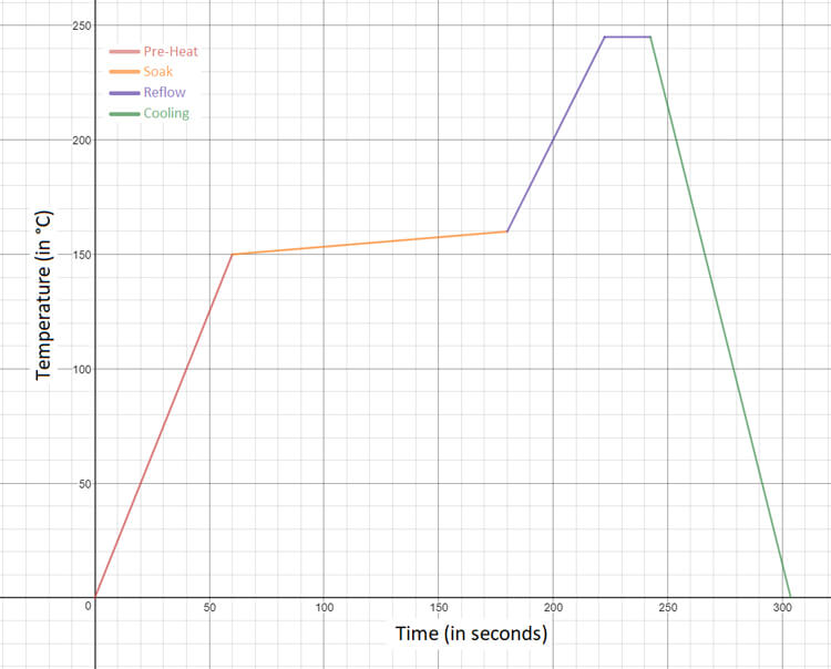
The main concern in reflow soldering is that components must withstand high levels of heat for a more prolonged period of time than what would be required for either wave or manual soldering. The vast majority of modern SMT components are designed with these heat profiles in mind, but many through-hole components are not suited to reflow soldering for this reason. PCB Assembly Company’s standard reflow cycle is described by the graph below.
| Pre-heat | to 150 °C | in 60 seconds |
| Soak | from 150 °C to 165 °C | in 120 seconds |
| Reflow | Peak temperature 245 °C | hold for 20 seconds |
| Cooling | –4 °C per second | to room temperature |
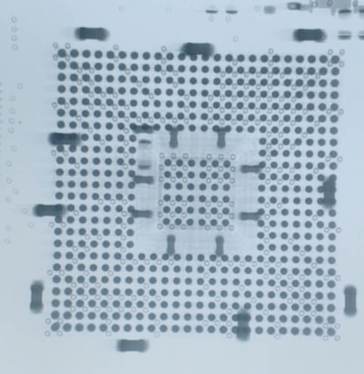
After a reflow cycle, any boards including BGA, QFN, or other lead-less package types are sent for X-Ray Inspection; this service is included by default on all Bittele quotations which include such parts.
X-Rays penetrate the silicon of an IC package and reflect from the metal connections underneath, forming an image of the solder joints themselves that can be analyzed by advanced image processing software similar to Automated Optical Inspection (SMT AOI Machine). Higher-density features in the captured area create a darker resulting image, allowing for quantitative analysis to determine quality of the solder joints and compare against industry standards.
Not only does X-Ray inspection detect issues in PCB assembly, but the analysis of an X-Ray image can help to determine the root cause of a given defect, such as insufficient solder paste, skewed part placement, or improper reflow profile.
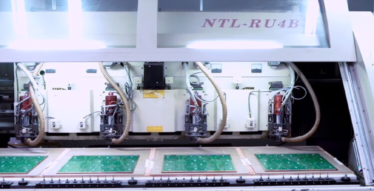
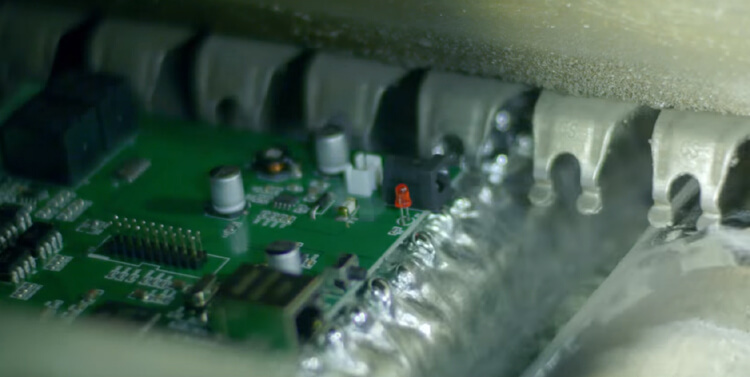
Wave soldering is a method of PCB Assembly that involves sending boards on a conveyor through a “wave” of molten solder. The solder bonds together exposed component pads and leads while wicking off of the bodies of components and the solder masked bulk of the board.
Wave soldering has fallen somewhat out of favour in the PCB assembly industry in recent years, at least in comparison to its past prevalence. The growing popularity of surface mount parts and High-Density Interconnect (HDI) PCB layouts make reflow soldering the method of choice for a majority of projects, and manual soldering can be used to take care of the typically few components not suitable for reflow. That being said, wave soldering certainly still has its place. For legacy boards requiring high proportions of Through-Hole Assembly, as well as boards incorporating large connectors with very high pin counts, wave soldering is often still the most efficient method for PCB assembly.
PCB Assembly Company should recommend that clients design for reflow soldering as often as possible since wave soldering does require more strict controls in design than reflow soldering. PCB Assembly Company’s process engineering team performs a thorough analysis of the PCB design before any wave soldering job, and will bring up any potential complications with a client in advance, but this does require additional time and cost compared to a reflow soldering project.
Manual soldering is generally used when a PCB design incorporates some parts that are not suitable for either reflow soldering or wave soldering. For example, a majority surface mount PCB might include a few through-hole components, and wave soldering these few parts would unnecessarily drive up the cost of production. PCB Assembly Company employs a staff should be highly skilled manual soldering specialists to take care of any such requirements, It's better to provide consistent and reliable workmanship even up to IPC-A-610 Class 3 Standards.
While PCB Assembly Company’s manual soldering specialists are incredibly proficient at their tasks, they are still subject to certain human limitations that do not apply to automated assembly methods. The most common manual assembly restrictions are listed below:
Multiple-row connectors (more than 2 rows) cannot be manually soldered since the tip of a soldering iron will not fit between rows; these devices are usually wave soldered
BGA, QFN, and other lead-less packages cannot be manually soldered
Part-to-Part Spacing* and Part-to-Hole Spacing* requirements must be carefully observed, and an additional margin of 5 to 10 mil is recommended around any manual assembly parts
Pad and Hole Size* requirements must be strictly followed, and an additional margin of 10% is strongly recommended for the SMT pad-to-lead ratio of manual assembly parts
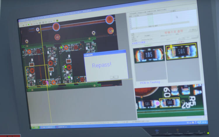
As noted above, inspections are carried out after every individual stage of the PCB assembly process to better localize the source of any error. PCB Assembly Company views these intermediary inspections necessary but not sufficient to fully guarantee the highest in quality of workmanship, as is their mission, and as such they always perform a thorough final inspection on the fully finished boards at the end of the process.
These final inspections always include visual inspection by PCB Assembly Company’s highly experienced quality assurance team, and Automated Optical Inspection (AOI) for complex or high-volume projects. They'd better also provide additional services such as Functional Circuit Testing (FCT) and In-Circuit Testing (ICT) upon client request. The more involved testing methods of ICT and FCT will require some additional lead time and labour cost depending upon the specific requirements for a given project, but can relieve the need for involved product testing on the client end.
The importance of SMT testing
SMT inspection is an important step in improving the quality of SMT products, it can improve product quality, and strive to achieve "zero defect."
The cost of assembling to the instrument and finding the fault is several times the cost of finding the fault when assembling the printed circuit board;
And the cost of finding the product after the product is put into the market will be hundreds of times the cost of finding the fault when assembling the printed circuit board.
In order to ensure the quality of SMT products, it is necessary to carry out effective testing, timely detection of defects and failures and repair, thereby effectively reducing the manufacture of products and failures caused by the cost of repair.
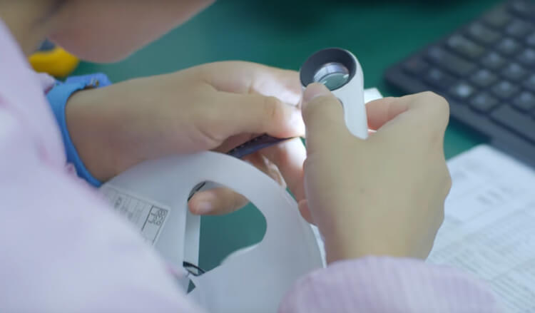
Another reason is nowadays more and more components are very small. some small components already can't identified by human eyes, like 0201,01005 it's too small to see the model number , direction by human eyes, need check by machines camera.
ICT tester
ICT is In Circuit Tester English abbreviation, the Chinese meaning is the online tester, is the modern electronic enterprise essential PCBA (Printed Circuit Board Assembly, printed circuit board assembly) production of test equipment.
ICT use, high accuracy of the measurement, the detection of the problem clear, even if the general level of electronic technology workers to deal with the problem of PCBA is also very easy.
The most basic instrument used for electrical testing is the On-Line Tester (ICT), which uses a component-level test method to test each component on the assembled circuit board.
ICT can be divided into needle bed ICT and flying needle ICT.
Flying needle ICT basically only static test, the advantage is no need to make fixture, the program development time is short.
Needle-type ICT can be simulator function and digital device logic function test, high failure rate.
In the SMT production line, the time on behalf of the efficiency.
The use of ICT can greatly improve production efficiency and reduce production costs, online tester detection failure coverage of up to 95%, its reasonable configuration in the production line can be found as soon as possible manufacturing failure and timely maintenance, or timely adjustment of the production process, Effectively reducing the cost of manufacturing defective products and repairing.
Keywords:
JUKI RS-1R Pick and Place Machine, JUKI RX-7R Pick and Place Machine, JUKI RX-8 Pick and Place Machine, JUKI RS-1R SMT Assembly Line, JUKI RX-7R SMT Assembly Line, JUKI RX-8 SMT Assembly Line.

Contact: Tommy
Phone: +86 13691605420
E-mail: tommy@flason-smt.com
Add: No.94,Guangtian Road,Songgang Street,Bao an District Shenzhen China